
| Contents |
| Dragon HW |
| Dragon SW (DDOS) |
| Dragon SW (OS9) |
| Dragon Projects |
Adding a Sound Chip
Design note: The following circuit can be interfaced directly to the cartridge port using the P2 line as your address decode source (AD in this article) which maps the device at $FF40:41 in the Dragon's memory map. However, in order to attach other peripherals to the machine (like the disk controller) you will need additional circuitry to provide the AD signal, these and other address decode possibilities can be found in the address decode section.
As previously mentioned, the other method of generating sound on a computer commonly used is by the use of a dedicated sound chip. This will be responsible for generating the required noise, leaving the processor free to continue with other things. They are also far more versatile, and offer multi-channel sound (some in stereo).
The sound chip I have attached to my Dragon is the SAA-1099 chip. It offers 6 channel, stereo sound and has to be the most under-used device I have ever added. It's been sitting on my machine for about 3 years, and short of getting the thing to work in the first place has never been used. Principally, because it's a bit complex to program, you have to deal with it in terms of frequency & amplitude, and it goes into attack/decay of sound waves etc. It's all documented in the data sheet, and one of these days I will get round to attempting to understand it. Also, because it's a fairly powerful chip, you would need a good flexible piece of software to get the most out of it. Therefore, if you do go ahead and build it, a good knowledge of all things musical is essential, and all I can offer is a couple of test routines which make some cheerful beeping noises.
The chip itself sells for about #10, and is designed to interface directly to a computer's databus (not a PIA job!), specifically the MC68000 series. It's an 18 pin device, with the pinout described as follows:
Pin #   Signal  Description

  1     WR~     Write enable. Enables the device
                to read the data currently on the data bus. The chip is write
                only, and this line connects via an invertor to the 6809's E
                line which will be high when the bus is stable.

   2    CS~     Chip Select. Connects to an
                appropriate chip select from your address decode logic - P2 if
                attached directly to the cartridge port.

   3    A0      Address line A0. Connects to
                Dragon's address line A0.
   4    RH O/P  Right channel sound o/p.
   5    LH O/P  Left channel sound o/p.
   6    IREF    Reference current. Connect via a
                10K resistor to +5V.
   7    DTACK~  Data Transfer Acknowledge. Output
                to 68000 series processors to indicate data transfer
                successful. Not connected on the Dragon.
   8    CLK     Clock. Connects to 8Mhz clock.
   9    Vss     0V.
  10    Vcc     +5V.
 11-18  D7-D0   Data/Address lines. Connects to
                the Dragon's data bus D0-D7.
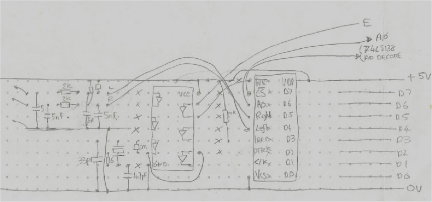
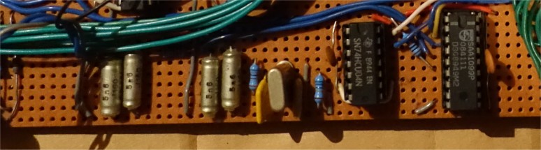
All that remains, is to provide the 8Mhz clock,
via a crystal and the output filtering on the 2 channel outputs. (See diagram).
Click on diagram to view full size.
Parts List
----------

SAA1099 IC   1 Off
74HC04 IC    1 Off
8Mhz Crystal 1 Off
2K Resistor  2 Off
820R         2 Off
10K          1 Off
6.8R         1 Off
5M6          1 Off
47pf Cap     1 Off
5n1 Cap      4 Off
Programming the device
The chip maps into 2 bytes of the Dragon's IO, dependent on which address decode line you use to enable it. It contains a set of registers, with which you program the chip with. To select the required register, write the appropriate register number to the odd numbered IO location. The register can now be accessed by writing to the even numbered IO location. As stated, all registers are Write Only, so there is no point in attempting to read from a location, you may corrupt the contents anyway.
As an example, suppose you connected the chips CS~ line to your address decode circuitry which activates when you read or write to locations $FF38-$FF3B.
In order to update register 2 with the value 45:
  POKE &HFF39,2  - select reg 2 using odd address
  POKE &HFF38,45 - write value to register
Getting hold of the data sheet is a definate must for this device. Listed in the table below is the register set from the data sheet which you may be able to work from, but there is a lot more descriptive information listed in the data sheet about all the chips capabilities.
Table 1 - Register Set summary
Table 2 - Register Set Descriptions
Sample Programs
The first program producing some warbling noises across both channels (if you connect the device up to a stereo system, you should hear it switch channels), and the second one creates a tone, which sounds like the hard drive on a PC taking off. I have included these more as a systems check to ensure your device is working rather as good examples of how to use it.
Note: Pressing RESET on the Dragon will have no effect, the chip will remain outputting the last sound prior to being interrupted. The only way to turn it off, is to explicitly turn the chip off, or turn the Dragon off!
  SSOUND.BAS
  ----------

1 HD=1
10 A0=&HFF3C 'DATA REGISTER - MACHINE SPECIFIC
20 A1=&HFF3D 'ADDR REGISTER - MACHINE SPECIFIC
21 POKE A1,20:POKE A0,3  'FREQUENCY 0,1 ENABLE (REG &H14)
22 POKE A1,9:POKE A0,200 'FREQUENCY OF TONE 1 = 200 (REG &H09)
23 POKE A1,&H15:POKE A0,0 'NOISE DISABLE (ALL CHANNELS)
24 POKE A1,&H10 'ETC,
25 POKE A0,&H23 'ETC
26 POKE A1,&H11
27 POKE A0,&H04
30 POKE A1,0
40 POKE A0,&H77
50 POKE A1,28
60 POKE A0,1
65 POKE A1,8
70 POKE A1,20:POKE A0,&H43
85 F=100
88 FD=3
100 G=15
105 GD=45
110 FOR H=&H11 TO &H44 STEP &H11
111 F=F+FD:IF F>240 OR F<10  THEN F=240:FD=-FD
115 G=G+GD:IF G>230 OR G=15 THEN GD=-GD
116 POKE A1,0:POKE A0,G
117 POKE A1,1:POKE A0,G
118 POKE A1,17:POKE A0,(&H55-H)
120 POKE A1,16
130 POKE A0,H
131 POKE A1,8:POKE A0,F:POKE A1,9:POKE A0,F+10
135 WAIT 50
140 NEXT
150 FOR H=&H44 TO &H11 STEP -&H11
151 F=F+FD:IF F>200 OR F<10 THEN F=200:FD=-FD
155 G=G+GD:IF G>230 OR G=15 THEN GD=-GD
156 POKE A1,0:POKE A0,G
157 POKE A1,1:POKE A0,G
158 POKE A1,17:POKE A0,(&H55-H)
160 POKE A1,16
170 POKE A0,H
171 POKE A1,8:POKE A0,F:POKE A1,9:POKE A0,F+55
175 WAIT 50
180 NEXT
190 GOTO 110

  NIMBUS.BAS
  ----------

10 A0=&HFF3C
20 A1=&HFF3D
30 POKE A1,2:POKE A0,255
40 POKE A1,10:POKE A0,100
50 POKE A1,&H11:POKE A0,4
60 POKE A1,&H14:POKE A0,4
70 POKE A1,&H15:POKE A0,0
75 POKE A1,&H18:POKE A0,11
80 POKE A1,&H18:POKE A0,139
90 POKE A1,28:POKE A0,1
100 POKE A1,9:POKE A0,0
110 POKE A1,&H10:POKE A0,64+16
115 POKE A1,&H14:POKE A0,0
120 FOR G=255 TO 1 STEP -4
130 POKE A1,9:POKE A0,G
135 WAIT 50
140 NEXT