
| Contents |
| Dragon HW |
| Dragon SW (DDOS) |
| Dragon SW (OS9) |
| Dragon Projects |
Dragon Train Control
Sadly not a lot has survived this particular project despite there being a lot of hardware involved - I found precious little of my schematics for this and the disk holding the software was corrupted (along with it's backup). So how much use this will be to anyone (other than just mild interest) is a bit doubtful.
My dad is a bit of a train buff, something I inherited a bit of. We had model trains in the loft and I decided it would be a good idea to try and computerise it with a Dragon. The plan was to kit out my spare Dragon 32 with the hardware to accomplish this, connected via my network to my main disk based D64 which would hold the software.
Hardware
The are two primary aspects to the train control system.
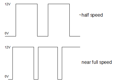
The first is in the actual control of the trains themselves. Traditionally each loop (or section) of track is fed (up to) 12V DC of power. The speed of each train is controlled by varying the voltage. One of the issues with this approach though is that at lower speeds (so lower voltage) trains have a habit of stalling due to either dirt on the track or purely how far away on the track is from the power source. So for the Dragon train controllers, we used a form of Pulse Width Modulation (PWM). This meant that the voltage would be consistent at 12V however the amount of time the voltage was "on" as opposed to "off" would vary.
The manual train speed controllers simply consisted of variable resistors - similar to those used in the Dragon's joysticks, I wanted the system to support up to 4 controllers. Originally I think we intended using the joystick interface for this but then chose not to in the end.
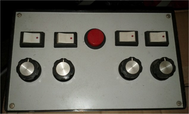
The buttons above each controller were for train direction whilst the big red button in the centre was the emergency stop - designed to raise an interrupt to the Dragon to shut all power down.
The second aspect to the system is the "accessory control". These allowed the switching of points, signals etc. Typically the accessories run on 16V AC - this helps avoid burning out point motors etc. should a switch become jammed. We opted to use the main 12V DC supply on the premise that the Dragon software would prevent this ever occuring (a bit of a misnomer since at least 2 motors were melted during development).
For this system I also wanted to include sensors on the track at various intervals so the system could know (roughly) where a train was at a given time. These were reed relay switches that would be set off by magnets glued to the bottom of the train engines. As a result, the accessories would be a mixture of ins and outs.
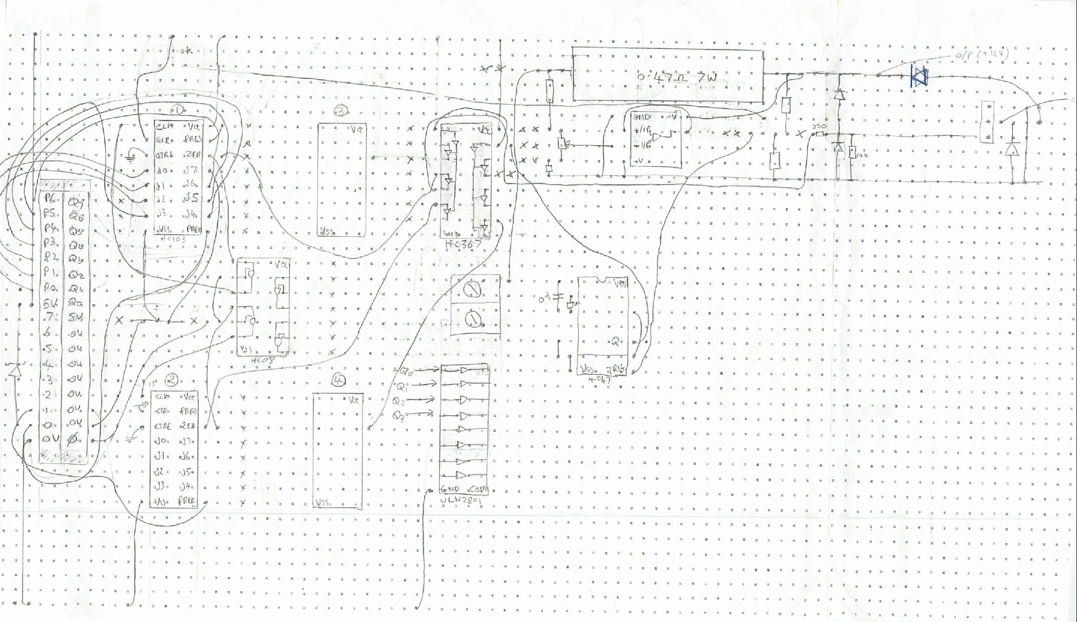
To avoid a mass of wiring accumulating at the controller (something that is common with main train systems), we designed an accessory controller. A number of these would be located around the layout (on the underside of the baseboard) linked to each other by a 10W ribbon cable - the "accessory bus". Each controller could address 8 (I think!) accessories. The module had a 6-bit address bus, enable line plus 12V power for the accessories themselves.
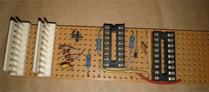
Unpopulated accessory module
The ribbon cables come in & out on the white connectors. From memory, I think the two chips were a 74LS138 (3-8 address decoder) and a darlington transistor array for switching the accessories.
I used two large stripboards to implement the train control system. The first, much like the one in my D64 sat above the main board inside the Dragon.
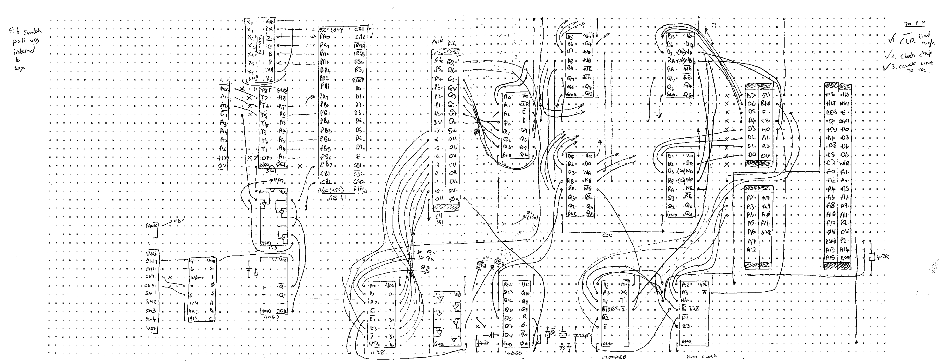
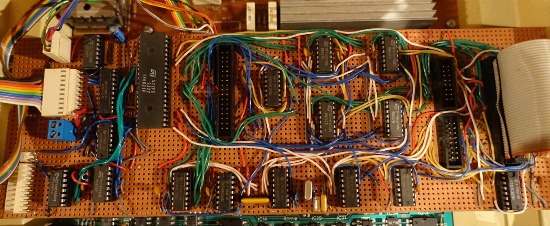
This board connects to the Dragon's cartridge port via the 40W ribbon connector on the right hand side. Sat next to this connector are the two IDC sockets for a network card and there will be some address decode logic nearby as well. Much of the logic between there and the empty IDC socket in the middle of the board was to do with the accessory control logic but I confess looking at it now I can't remember much about how all this worked! On the left hand side of the board (from top to bottom) is an additional power connector, the link to the accessory bus, terminals for the 12V switching supply for the accessories and finally the connections for the speed controllers.
The empty socket in the centre of the board is used to connect up to the second board which was responsible for the PWM generation and actual train control. Due to space contstraints, this sat on top of the D32's case.
The ribbon cable from the first board is attached to the connector on the left hand side - again I confess I can't remember how some of this logic works. The main 12V supply is connected via the two centre terminals and then there is space for the 4 channel controllers themselves - only one is populated here.
Throughout this design one of the things paramount on my mind was in keeping (and ensuring it was kept) the "heavy duty" 12V supply away from the logic (I seem to remember it was rated at something like 4A) and I remember there were a few safeguards built in to try to ensure that even if a fault condition arose, this could not feed back into the Dragon.
Software
The software was split into two components. The first was the LAYOUT software which was a mouse driven application (normally executed on my D64) used to design the layout. This was put together using a set of fixed "blocks" eg. a straight, a curve, a RH point etc. This included defining to the system the identification and type of each accessory connected to the accessory bus.
This technical note describes more about how the layout designer worked. When the design was complete, it was exported into a format suitable for use with the main train control application.
The main train control software could now be used. After the layout definition had been loaded, a schematic was displayed on screen, updated using the information received from the accessory bus the position of all the points on the layout. The train controllers could now be used to drive the trains around the layout. Each time a train passed a track sensor, the on screen schematic would be updated to show the position of the train. Points could be changed via the use of a light pen connected to the joystick port. Alternatively, hot keys on the keyboard could be used to switch them and change signal states etc.
This was the manual mode of operation however I also provided an automatic mode. This provided a simple scripting language which could be used to program a train to follow a preset sequence. Using the track sensors, it was possible to change points, signals etc. whenever a train triggered a given sensor. The language also allowed the speed and direction of each train to be programmed.
The train control manual I wrote described all this in detail.
Most of the software was written in BASIC with a few assembler routines included where necessary. One key one was in the handling of the track sensors. In order to retrieve the state of any given accessory, it was necessary to program it's address (via the 6 address lines on the bus), then read the state back. In order for this to work, I hooked up the polling of all the track sensors to the 50hz IRQ routine. This meant that a train, running at top speed would need to activate a sensor for at least 20ms in order for the display to be updated. I did some trials which indicated that it did always detect a train passing a sensor but since the project was never fully completed I was never entirely sure.
End of the line
Functionally the hardware principals were sound, the train controllers worked (at least in manual mode) and I had 3 or 4 points and a few sensors connected up via 2 accessory modules. Unfortunately though I started to find building the 6 odd accessory modules quite tedious (having made 3) and our local modelling shop seemed to be perpetually out of stock of things like point motors which I needed to progress much further. I think at the end I had about half of the layout cabled up for accessory modules & track sensors by then I was being distracted by other things and within a few years had moved out. I strongly suspect (based on how my main expansion board has fared) that the stripboard & my soldering probably haven't held up that well this past 15 odd years plus the loss of all the software means this will never be ressurected.