
| Contents |
| Dragon HW |
| Dragon SW (DDOS) |
| Dragon SW (OS9) |
| Dragon Projects |
Cartridge Port Design
Up2Date '91
The most expensive part of expanding the Dragon is always the initial setting up. Once done, additional devices can be relativly cheaply added to the main board.
The main doorway of adding onto your Dragon is via the cartridge port - an alternative is to piggy back your board on the CPU . It gives access to most of the important things in the machine without removing chips inside and by unplugging the board can be returned to 'normal' at any time. Unfortunately though its not a standard connecter so its not too easy to get hold of the edge connectors designed specifically for the Dragon. On all my machines I use cut down PC boards from Tandy at about #4 each. These have 72 positions so will need to be cut down equally each side with a hacksaw. Cut down until about the last connector each side and then file down in order to ensure a snug fit into the cartridge port. This isn't too difficult, I've done two of them without messing them up.
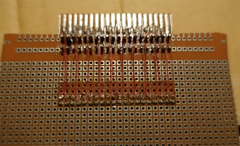
The only problem with this connector is that is is not too nice to wire up. None of the contacts are connected together making it extremely difficult to link devices together. I eventually used a wire wrap system. This is a Maplin purchase for #7.45 which is fairly steep for what it is but will probably find a number of uses. This is composed of a pen with a small reel of thin wire which you wrap around the leg of a component, and link it to the next one which again you wrap around etc. The idea being that when you solder the component the insulation on the wire melts creating a good joint. You do need a good hot soldering iron however, (the one I had was just not up to it). This takes some practice. The end idea being that all of the 40 contacts on your edge connector are linked to a 40 way IDC connector (similar to the printer port which is 20 way). That is only half the story. If you've got a disk system (which you probably have) then you'll need two IDC connectors linked. The order you do this is VERY important. Turning the board up-side down there will be two rows of holes near the contacts. One connecting the bottom set of contacts and one for the top set. Place the IDC connector on the top side with the notches facing away from the contacts. Looking from the underside again the contacts for the bottom of the edge connector need to be linked to the front IDC pins and the contacts for the top need to be linked to the back IDC pins (see diagram). This needs to be the same for the other IDC connector.
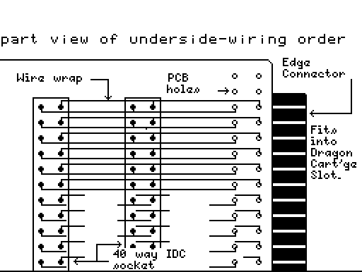
You should link them altogether in one go using one length of wire wrap per contact. When using the wire wrap ensure that the wire protrudes through onto the top side and connects with the upper contacts. The order of connecting which pins is important because as I found out by not following this order, when you come later to connect up the disk cartridge all the contacts get flipped round - which is not good.... Once this is accomplished you will have an edge connector board with two 40 way IDC connectors ready for expansion.
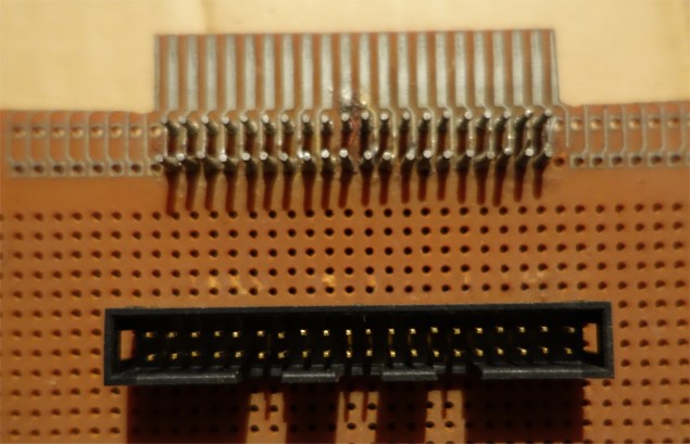
This photo is actually from another project which only required a single
40W IDC socket but it's just an extension of this
Now comes the customary cautionary note: It is possible to do severe damage to the Dragon at this stage, or later, by getting things wrong so check things out. Eg. A 12v line connected to the processor's lines probably wouldn't help it along the way. I've had mess ups myself with 5V lines connected to data lines, nasty screens full of wavy lines on switch on etc. but I've not killed a machine (yet!). If you're a multiple Dragon owner it might be wise to say test out your boards on a D32 instead of a D64 since the replacement cost is much less. However there is always some risk whatever you do - take your life in your own hands as they say. Having just terrified you to death, take your newly made board having checked it carefully, plug in, switch on and absolutely nothing should happen (out of the ordinary that is!).
68xx Interface Design
This time we'll deal with the theory behind connecting an IO device to the Dragons cartridge port. Following last time I described one possible way of making access to the cartridge port easier - by bringing out the lines onto two 40 way IDC connectors. I'm going to concerntrate on connecting an MC6821 PIA to the port because its relativly easy, and designed for connecting to 68XX processors. The Dragon has in fact got two of these internally. The device could however just as easily be another 68XX interface device eg. the 6850 serial chip for adding RS232 to a Dragon 32. Essentially the 6821 provides two 8 bit ports - like those used on the BBC micro & C 64's user ports. Hence you can effectivly connect these back-to-back to port data between machines. The Parallel Comms document further covers this and gives some more information on programming the device.
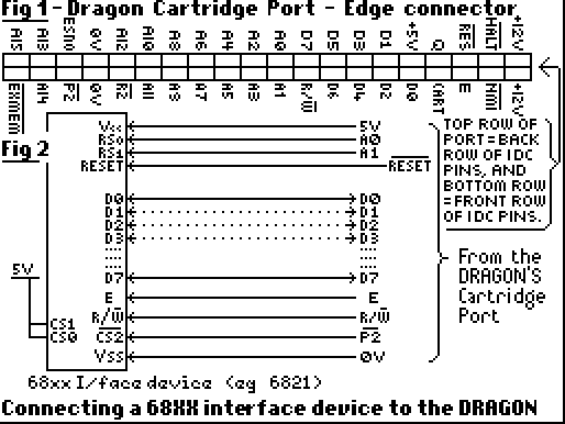
As regards connecting this device to the computer it is worth looking at what happens when you access an IO device. There are a number of important processor lines all on the cartridge port which come into play. Those labelled D0-D7 (data bus), A0-A15 (address bus), R/W (read/write line) and E (clock line). Note on the diagrams the R/W line is shown with a line above the W. This indicates inverse logic ie. where you would consider binary 1 as +5v and 0 as 0V the reverse applies 1=0V and 0=5V. Consider the following command:
POKE 65280,255
The following (in simple terms) now occurs. The E line is the computers internal clock. It changes from 0V to 5V at a fairly fast rate (about 1,000,000 times a second - I think!). For one of these pulses the number 65280 is represented in binary on the address bus (A0-A15) and the number 255 is placed on the data bus by the processor. Also at this time the R/W line goes to 0V indicating a write (if the command was PRINT PEEK(65280) for example then the R/W line would be high indicating a read and the IO device would be expected to put the data on the data bus). Hence this provides all the information a device needs to operate.
When you look at the pinout of a 6821 (or a 6850 both available from Maplin), you can find most of these lines on the chip apart from all of the address bus. This is because it doesn't need all of the address bus to operate. The 6821 only provides 4 locations to read or write to, so only the bottom two address lines are provided (marked RS0 & RS1) which provide 4 different binary combinations (0:0, 0:1, 1:0 & 1:1). The rest of the address bus is decoded into one line (called a chip select) to give a specific location in memory where the device would appear. For example if you wanted it to appear at location 0 then all you would need to do is check that when all the address bus lines from A15-A2 are 0, you activate the chip select line. Likewise at location 1024 you need to check the following combination:
  A15 14 13 12 10 09 08 07 06 05 04 03 02
   0   0  0  0  1  0  0  0  0  0  0  0  0
and only then activate your device.
Fortunatly, on the Dragon if you only want to connect one device like a PIA you don't have to decode this yourself, a line is provided called P2 to enable your device. The disadvantage is that this is used for the DOS so you'll probably need to decode anyway. I'll go more into address decoding another time.
So, in order to connect up your PIA, its a simple case of linking the D0-D7 lines from the cartridge to D0-D7 on the PIA chip, the E line, R/W line, and the address lines A0 & A1 to RS0 & RS1. There are 3 chip select lines on the PIA called CS0, CS1, & CS2. Only one of these is needed so the other two should be permanently enabled. Note once again the line above the CS2 line so to enable the device to be selected correctly it should be connected to the P2 line which also uses negative logic. CS0 & CS1 should be connected to +5V. The only other line which needs to be connected is the RESET line which resets the chip when you press the reset button. Not forgetting the power supplies +5V and 0V (on the chip VCC=5V & VSS=0V). And that is all there is to it. Once connected up the device will appear at location $FF40,1,2,3.
I described last time how, in theory to connect a MC6821 PIA device to the Dragon's cartridge port. I'll spend some time this issue concerning the practicalities of attaching the chip. In part 1, I went through how to bring out the 40 way cartridge port onto something more useful - a 40 way IDC connector. In fact, there sould be two connectors on the board, one for later re- connection to a DOS cartridge.
The IDC connector can be linked to the main board containing the components via appropriate IDC sockets attached to ribbon cable. The IDC/ribbon cable combination is a neat way of connecting devices requiring many wires. However it is not too easy to crimp the connectors onto the wire. You cannot simply press them together, nor use a pair of pliers. Ideally you'll need access to a good vice to clamp the connector together.
All of the extras bolted on to my Dragon are on stripboard. These are essentially plastic based boards with a matrix of holes spaced evenly apart. On the other side of the board copper strips run along in line with a set of rows. Components are placed on the insulated side with their pins protruding through the holes, and soldered to the copper tracks underneath. Wires and such like can then link various components together, along with the copper tracks themselves. Quite often the tracks do not go where required (for example underneath a chip, all the opposite pins would end up connected),in which case the tracks can be easily cut by use of a small drill bit. There are various sizes of stripboard available depending on where you look. I use the largest size board Maplin make (117*38 holes) because it sits quite nicely above the main board in the Dragon. When you come to ribbon cable the stripboard and the cartridge connector use the shortest possible cable you can get away with. Bear in mind the 'E' clock line I mentioned last time changes state very fast and by making the wire to long will mean the pulse never reaches the other end! You'll need an IDC connector at one end for the cartridge connector but what you use at the other end is down to you. You could use another IDC connector/socket assembly or a PCB Transition Header. The latter attaches the cable permanently to the strip board, is cheaper and reduces the amount of contact resistance on the cartridge lines. However it is harder to clamp, and not so easy to work with once attached. Strip board design of circuits takes some time. Its NOT a good idea to just jump straight in. If you've got a printer then its a good idea to print out an array of dots the size of the stripboard. A simple BASIC program should achieve this:
10 FOR X=1 TO (No. of lines across)
20 FOR Y=1 TO (No. of lines down)
30 PRINT #-2,".";
40 NEXT Y
50 PRINT #-2
60 NEXT X
Once printed you can design your layout in pencil. Work from a circut diagram. The lines running across will be linked via copper tracks. Mark cuts on the track with an X. All tracks normally under chips will need to be cut. Its a good idea to socket all ICs. That way you can solder without fear of damaging the chips. The IDC ribbon cable will come ideally onto the board at the centre on the right hand side of the board if you are going to mount it internally. Since you cannot cut the tracks inbetween where the ribbon cable comes onto the board using the technique I mentioned before because the connector usses two adjacent lines, the track will need to be cut with a craft knife. Try to take as little space as possible in order to preserve space for future expansion.
If you are planning a design which involves 68XX interface devices, then you could wire up one following the circuitry shown last time and see if it works.
A quick word about software. Remember that whatever you design and build, that its probably unique. No-one else will have something quite like it and therefore you'll have to write the software that controls it. Although you can use some devices from BASIC, more than likely machine code will need to be used. Obtaining the data sheet with the device is almost a must for learning how to program a device. In general,its a good idea to test the device first in BASIC, where you can easily fathom out if its the device that's not working or the circuit.