| Contents |
| Dragon HW |
| Dragon SW (DDOS) |
| Dragon SW (OS9) |
| Dragon Projects |
ADC/DAC Samplers
Up2Date '94
Back in the early days, the Dragon would be criticised: 'it's got no sound chip!' and therefore musically wise could be classified with a Spectrum - a beeping machine. However, the Dragon was light years ahead - being fitted with its own digital to analogue convertor (DAC) something which your self respecting Atari/Amiga owner woundn't be without. The DAC on the Dragon is well used. Considering it's really only 6 resistors, uses include cassette output, sound generation & joystick reading. What it's noted for though is in the area of sound. A DAC does what it's name suggests - converts a digital binary number into an analogue signal, a varying voltage. Therefore, feed 000000 into the convertor and you get 0V out & 111111 returns +5V. Binary values in between return voltages between 0 and 5V.
Change the values sent to the DAC fast enough & feed the resulting signal to a speaker and you get sound. The Dragon feeds a set of numbers first obtained from it's ROM to create musically notes, but where DACs have really come into their own is with sampling - feeding sound into the computer (via the opposite to a DAC, an analogue to digital convertor (ADC)), and playing it via a DAC.
Unfortunatly both playing back samples and creating music this way has one drawback - it's very processor intensive. Sound generation just can't be left to it's own devices, it needs constant attention by the processor and hence the lack of games which play music in the background.
This is where a dedicated sound chip comes in. These deal with all the sound generation themselves, all the computer has to do is tell them what note, octave, channel etc. and they get on with it themselves. By building up a table of the data to control the chip, you can program the Dragon to send it to the chip under interrupts giving true background music.
So there are 2 ways to enhance the musical capabilities of the Dragon - adding an ADC to move into the world of sampling or a dedicated sound chip. Over the next few editions I'll try to explain how to connect both these devices to the Dragon and writing software to use them.
ADCs, samplers the digital bit
An ADC was the first extra peripheral I bolted onto my Dragon after I'd done the address ecoding. That was about 3 years ago, and two software re-writes later I've got another couple of programs in mind to use the thing. The secret is not in the chip itself, but the software driving it and how versatile that is. A nice chunk of memory is useful as well.
The chip I use is a ZN448 which goes for about £9 in Maplin. Its a fairly simple chip, with only 18 pins, and 8 of those are data lines. It interfaces to an IO port (another PIA job), although with a bit of persuassion I believe you can connect it direct to the processor's data bus. The digital side consists of the following signals:
  Pin(s)     Signal    Description
   9          GND      connects to 0V
  10          VCC      connects to +5V
  11-17      DB7-DB0   8 bit digitized output.
                       Connects to PIA input
                       port, preferably PA0-PA7.
   1          BUSY     goes high to indicate ADC
                       is busy sampling.
                       Connects to PIA input
                       control line CA1.
   4           WR      when the signal goes high
                       it tells the ADC to begin
                       sampling.
   2           RD      output enable. Enables
                       the ADC's outputs when
                       high. Can be tied to +5V
                       for our purposes.
   5          R EXT    connects to -5V(see
                       below)
   7          V REF IN ADC's sampling reference
                       voltage. Connect to +5V
                       via a 390R resistor.
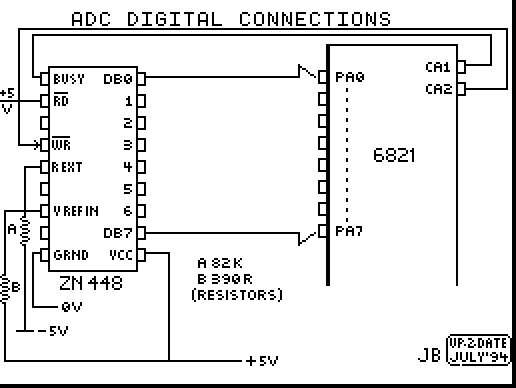
and that completes the digital side. The important lines are the data output lines which contain the digitized data for the computer to store/process and the 2 control lines BUSY & WR.
Principally, when you want to sample something you pulse WR high which starts the sample. Whilst the ADC is sampling, it pulls BUSY high. Therefore by connecting these lines to CA1 & CA2 on the PIA, you can start a sample simply by reading the ADC, and test CA1 until it indicates that the ADC is ready. You then read the sampled byte, hence setting off another sample etc. etc.
The R EXT pin needs to be connected to -5V via an 82K resistor, which unfortunatly isn't connected to the cartridge port.
On D32's, you can connect a flying lead to the main board on the -5V rail (should be pin 1 of all the 16K DRAMS but its worth checking with a multimeter).
On D64's there is no -5V rail, only a -12V. Therefore again you can connect a flying lead to a -12V source on the main board (pin 7 on RS232 port is connected to -12V line) however it will then need regulating down via a zenor regulator.
In both cases, it's preferable to avoid trailing leads to the main board and generate the -5V from existing power rails. On my D64 I use a 555 timer circuit to generate -5V from +12V, but this is perhaps a little excessive. The data sheet for the device suggests several charge pump circuits to enable the temporary generation of -5V. These work by charging up a capacitor when the chip is not sampling, then discharging it into the R EXT pin when sampling begins. I've included one of the circuits which, although I haven't personally built it, I am assured it works by a friend who has. All that is required is an invertor IC, 2 resistors, a diode & a capacitor.
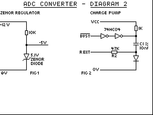
The capacitor value is based on the clock value of the chip (which I'll deal with next time) given by the formula:
R2 X C1 > 100/clk
where R2=47K, & the clock at a minimum 100khz so something like a 10nF capacitor should suffice (unless my maths is horribly wrong).
ADCs, samplers the analogue bit
By far the worst bits to fiddle with to my mind. Having connected up the digital side of the ZN448, all that remains is the interface to the analogue signal.
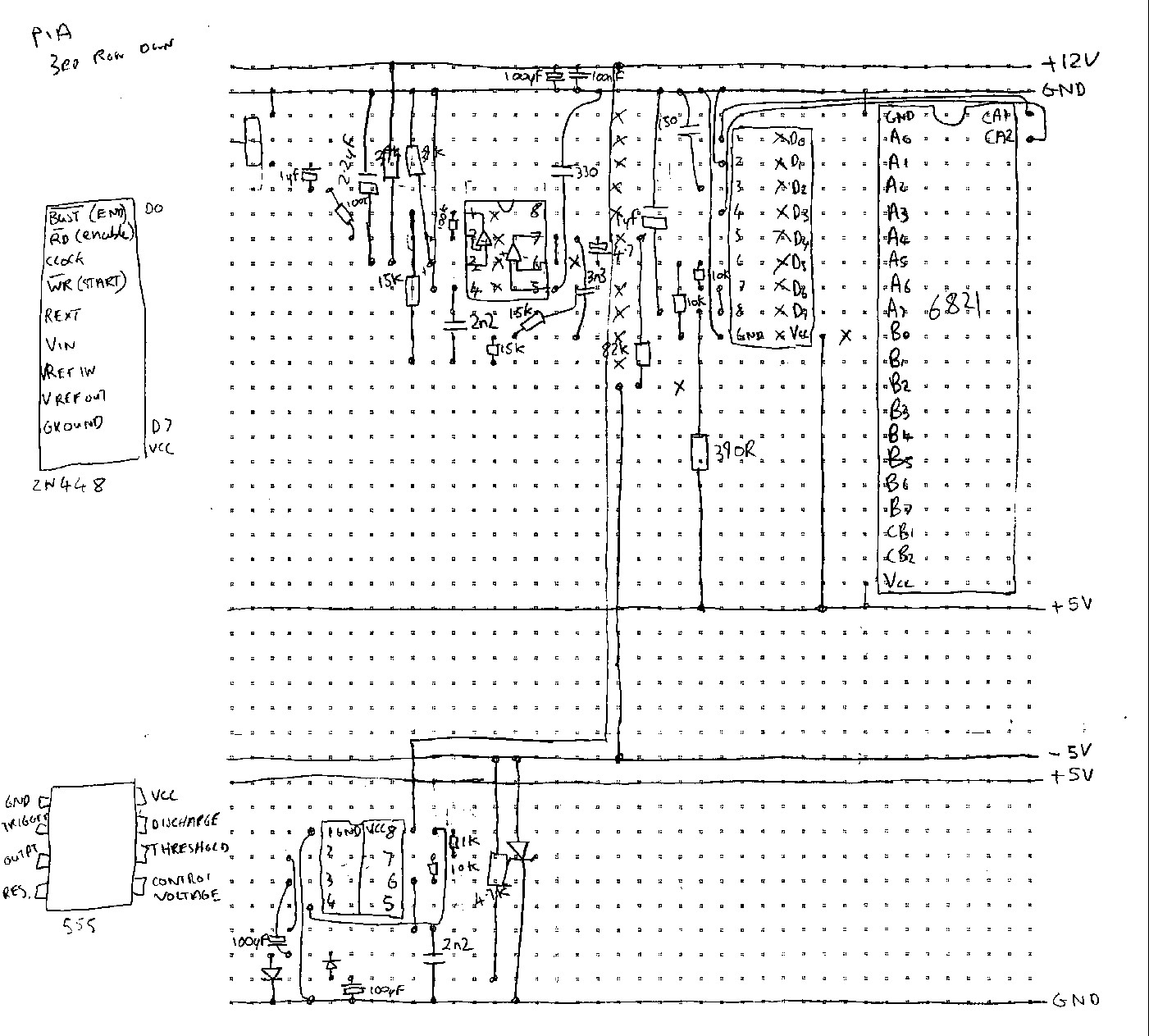
There are only a couple of unaccounted for lines on the chip, and as usual they are the most complicated. This design for a sampler is the third one I've been involved in and all the analogue stages have been slightly different, so all I can do is use the circuit my particular machine uses because it's the only one I've got access to and the only one that is documented on paper. Suffice to say, it originated out of a magazine article on samplers for the BBC micro.
 Pin(s)    Signal   Description
  3         CLK     sets the ADC sample rate.
                    (see below).

  6        V IN     the analogue input signal
  8        VREF OUT not used
The CLK pin can, at a bare minimum be connected to ground via a 150pF capacitor, and indeed this is how mine is connected. However, a better method would be to connect the Dragon's E clock line to it via a buffer. If you've used the charge pump circuit to generate -5V, then one of the spare invertors on the 74HC04 will suffice.
V IN connects to the input signal, and although it can be connected directly to an audio source, it should really be filtered and biased correctly and all sorts of other things that I don't know the meaning of. Therefore, the remainder of the circuit constitutes an op-amp (LM358 in my case) and a multitude of discrete components. Since I don't know what it all means, I present the circuit without further comment.
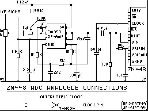
**********
PARTS LIST
**********

Part No.        Qty

ZN448 (ADC)      1  ( + chip socket)
LM358 (OP-AMP)   1  ( + chip socket)
82K              1
390R             1
10K              2
15K              3
100K             2
39K              2
1uF elect.       2
150pF polyst.    1
4.7uF elect.     1
330pF polyst.    1
3n3 poly. layer. 1
2n2 poly. layer  1
2.2 elect.       1
10K Preset       1

3.5mm jack skt   1  or other input socket

Zenor -5V Regulator

10K              1
5.1V Zenor Diode 1

Charge Pump -5V Circuit

1K               1
47K              1
10nF             1
1N914 Diode      1
74HC04 Invertor  1
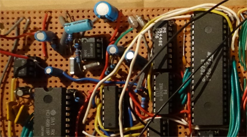
Here the ADC (ZN448) is sat next to the A side of the PIA with the 358 input op-amp a little further away. Initially (and as reflected by the code in this article) I used the Dragon's 6-bit DAC for playback however sometime later (probably to improve playback quality) I fitted a dedicated 8-bit DAC - the ZN426 sat on the B side of the PIA. That other 8-pin chip to the far left of the photo is the output op-amp for this device.
ADC SAMPLE PROGRAMS
At the risk of becoming repetitive (and totally boring) there are loads of things you can do with an ADC/DAC combination. From basic recording, playing & storing samples to echoing & composing your own music (I've heard an Amiga do it, so why not a Dragon?)
Here are a couple of samples:
Predefined labels for ADC PIA
@CRA - PIA Control register A
@DRA - PIA Data register A
1. Record/Playback routine
This routine enables a sample to be recorded & stored in a block of memory at a given speed (1 is the fastest, 255 the slowest).
EXEC 567,start_memory,length,speed
The routine can then be played back via:
EXEC 490,start_memory,length,speed
the speed should have 2 added to it to match the recorded speed.
Start_memory can be anywhere in the Dragon's normal RAM, and the length up to the top of the machine's RAM. Remember not to hit the stack though! To gain maximum memory therefore, use something like:
PCLEAR1:CLEAR 100,6999
EXEC 567,7000,25760,1
gives about 25K of sample space.
On D64's you can make use of the extra 32K behind the Dragon's ROM. Therefore with the above PCLEAR/CLEAR statement:
EXEC 567,7000,58280,1
giving about 56K of sample space.
10 EXEC &H6C00
15 ORG 490
20 ALL
30 @PLAY PSHS U,A,B,X,Y  - playback routine
40 LDB #0         - set the Dragon's multiplexor
50 JSR $BD41      - to the internal DAC.
60 LDA $FF23      - and switch it on (AUDIO ON)
70 ORA #8
80 STA $FF23
90 BSR @PARAM     - get the EXEC parameters
100 ORCC #$50     - switch off interrupts
110 STA $FFDF     - switch to 64K map mode
120 @LOOP LDA ,Y+ - read a byte from memory
130 STA $FF20     - send it to the DAC
140 TFR B,A       - B contains the speed count
150 @WT1 DECA     - do nothing for the reqd. time
160 BNE @WT1
170 LEAX -1,X     - decrement the length count
180 BNE @LOOP     - if not zero, play another
220 STA $FFDE     - switch back to 32K map
230 @ENDPLAY PULS A,B,X,Y,U,PC - exit

240 @PARAM JSR $89AA - parameter routine
250 JSR $8E83
260 PSHS X
270 JSR $89AA
280 JSR $8E83
285 PSHS X
290 JSR $89AA
300 JSR $8E83
310 TFR X,D    - B = speed count
320 PULS X     - X = length count
330 PULS Y     - Y = start_memory
340 RTS

350 @RECORD PSHS U,A,B,X,Y - record
360 CLR @CRA   - reset the ADC PIA
370 CLR @DRA
380 LDA #47    - setup the control reg for CA2
390 STA @CRA   -   strobe on read
400 BSR @PARAM - fetch the parameters
410 ORCC #$50  - switch interrupts off
420 STA $FFDF  - switch to 64K map mode
430 LDA @DRA   - initiate ADC (dummy read)
440 @RECLP TST @CRA - test for CA1
450 BPL @RECLP      - wait until ADC ready
460 LDA @DRA   - load the sampled byte.CA2 strobe
470 STA ,Y+    - store
475 TFR B,A    - delay loop
476 @WT2 DECA
477 BNE @WT2
480 LEAX -1,X  - decrement byte count
490 BNE @RECLP - more to sample
500 STA $FFDE  - switch back to 32K map
510 PULS A,B,X,Y,U,PC
520 END @RECORD - quit
2. Echo Unit
This routine implements a simple echo unit. The program works by looping around a section of memory, using storing a byte, and playing the following byte. It also digitally 'echoes' the sound by means of bit shifting. Called by:
EXEC 490,start_memory,length
you don't need as much memory for this program, up to 7K for the best effects.
When run, the program will wait for the spacebar to be pressed. It will then clear the memory of any garbage, and begin the echo routine. Press the spacebar to stop the program.
10 EXEC &H6C00
20 ORG 490
30 ALL
40 @ECHO PSHS U,A,B,X,Y
50 CLRA         - init the keyboard column
55 STA $FF02
60 LDB #32      - test for bit 5
70 @NOYO BITB $FF00
80 BNE @NOYO    - loop until spacebar pressed
90 LDX #$8000   - delay to ensure spacbar is
100 @KEYBD LEAX -1,X  - released, so echo
110 BNE @KEYBD  - routine doesn't exit immediatly
120 JSR $89AA   - fetch parameters
130 JSR $8E83
140 STX >$FE    - start_memory
150 JSR $89AA
160 JSR $8E83
170 STX >$FC    - length
180 LDY >$FE    - clear the memory
190 LDA #128
200 @BLK STA ,Y+
210 LEAX -1,X
220 BNE @BLK
250 CLR @CRA    - init the ADC PIA for i/p
260 CLR @DRA
270 LDA #47     - enable CA2 strobe
280 STA @CRA
290 ORCC #$50   - IRQs off
300 CLRB        - enable sound mux for DAC
305 JSR $BD41
310 LDA $FF23   - switch the mux on
312 ORA #8
314 STA $FF23
320 STA $FFDF   - switch to 64K map mode
330 LDA @DRA    - initiate first ADC read
340 LDX >$FC    - X = length
345 LDY >$FE    - Y = start_memory
350 LDB #32     - B = test bit 5 (spacebar)
360 @LP1 TST @CRA  - test for CA1 (ADC ready)
370 BPL @LP1
380 LDA ,Y      - load byte from memory
385 STA $FF20   - play it through DAC
390 LSRA        - shift bits (lower volume)
392 STA >$FB    - temporarily store
394 LDA @DRA    - load the ADC byte (start next)
396 LSRA        - shift bits to prevent overflow
398 ADDA >$FB   - add to last byte to 'echo'
400 STA ,Y+     - & store
410 BITB $FF00  - test for spacebar
415 BEQ @OUT    - quit if detected
420 LEAX -1,X   - decrement length count
430 BNE @LP1    - loop if still some to go
440 LDX >$FC    - load up for next loop
450 LDY >$FE
455 BRA @LP1    - loop back around
460 @OUT STA $FFDE - switch to 32K map
470 PULS U,A,B,X,Y,PC  - quit
480 END @ECHO
These are two uses of the ADC/DAC combination. Play with the routine, changing the odd byte, or varying the speed can create some interesting results, even playing it backwwards (remember the satanic messages that are supposedly on a number of records if you play them backwards....)
Samples can be saved to disk using the normal SAVE/LOAD binary file commands if they are under 32K. To save samples which overlap into the 64K memory map, use the 64KLOAD and 64KSAVE routines listed several issues ago.
The samples are reasonably high quality, but unfortunately especially if you've only got 32K RAM to play with memory is the limiting factor. Obviously the higher sample rate, the more memory is required to store it. Utilising the main memory on the Dragon doesn't leave barely any room for a driver program to interface to the machince code EXEC calls. My first sampler system squeezed into about 3K with multi-loader programs. Off board RAM & lots of it is the only alternative. If you've built the RAM drive I've got copies of sample routines to record/play and load/save to disk from the RAM drive memory.
If quality is your main concern then these routines can be streamlined down. As an example, the ADC takes 9 of the Dragon's clock cycles to do a sample. Since there are probably more than 9 cycles in the sample loop, you could remove the TST instruction for the CA1 line, assuming the ADC will always be ready.
Download DASM source of sampler code
Download DASM source of echo code
Download DASM source for PIA RamDisc Sampling
